Here is a step-by-step guide on how to configure a Layer 4 virtual server on an A10 Server Load Balancing (SLB) appliance using the CLI command and GUI.

Configure a Layer 4 Virtual Server
Step 1. Enter Configuration Mode
Enter configuration mode by typing the following command:
configure
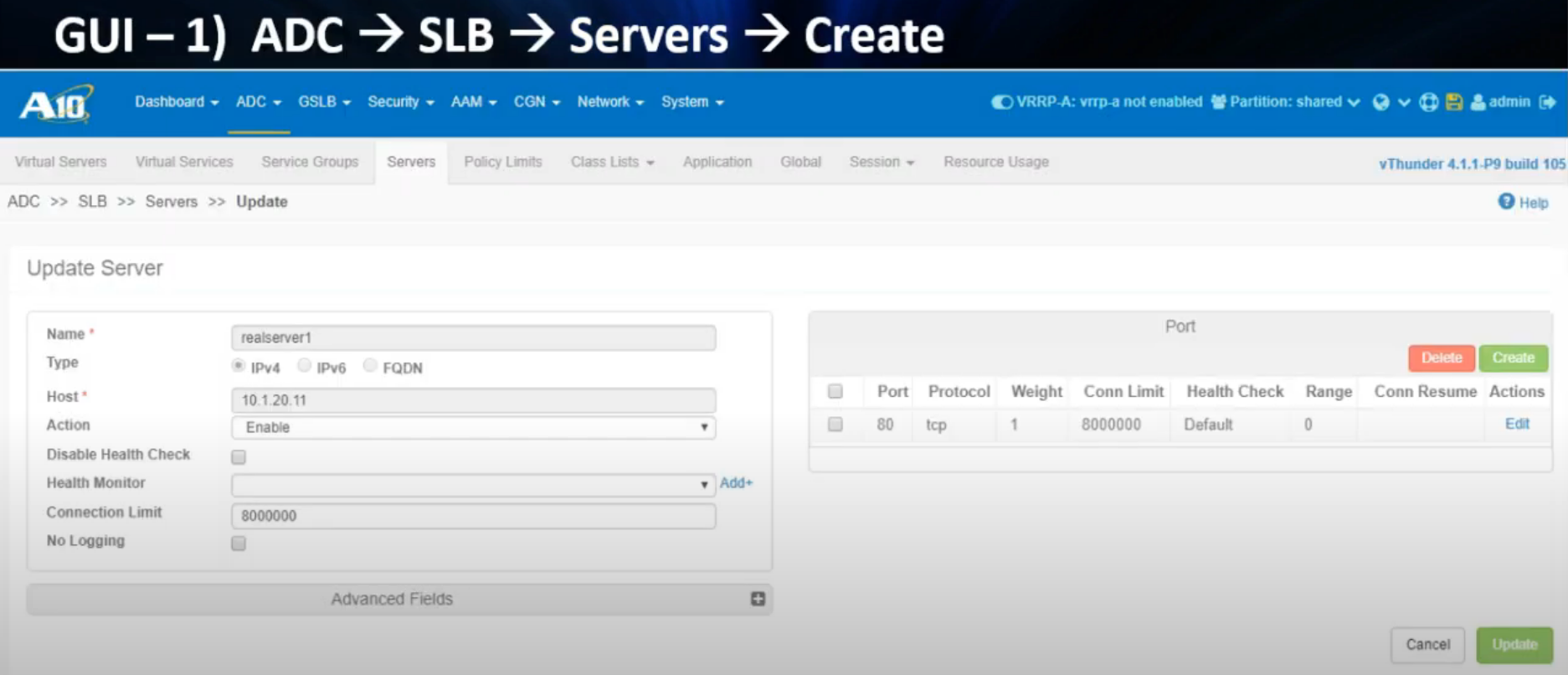
Step 2. Define Real Servers (nodes/pool members)
Must include object name, IP address or DNS name & port.
A Layer 3 default Health Check will be applied to the Real Server IP addresses.
A Layer 4 default Health Check will be applied to match the ‘port 80 tcp’ command.
- CLI
slb server realserver1 10.1.20.11
 port 80 tcp
slb server realserver2 10.1.20.12
 port 80 tcp
slb server realserver3 10.1.20.13
 port 80 tcp
 exit
 exit
- GUI
Step 3. Create a Service Group (pool/server farm)
Group of servers that fulfill a service.
Load balancing algorithm applied here. Round Robin is used by default.
- CLI
slb service-group webapp1_80 tcp
   member realserver1 80
   member realserver2 80
   member realserver3 80
   exit
   exit
- GUI

Step 3-A (Optional). Change the Load Balancing algorithm
Change the Load Balancing algorithm method if needed.
- CLI
Here are some of the common load balancing methods available on the A10:
- Round Robin: This method distributes incoming traffic equally among all available real servers in a sequential order. It is a simple and straightforward method and is commonly used as the default method.
- Least Connections: This method distributes incoming traffic to the real server with the fewest number of active connections. It is useful in scenarios where the real servers have different processing capacities.
- Weighted Round Robin: This method distributes incoming traffic to the real servers based on their weight. You can assign a weight value to each real server, and the traffic will be distributed based on the ratio of their weights. This method is useful when you want to control the proportion of traffic sent to each real server.
- Source IP Hash: This method distributes incoming traffic based on the source IP address of the incoming request. It ensures that the same source IP address is always sent to the same real server. This method is useful in scenarios where the client needs to maintain persistent connections to the same real server.
- Destination IP Hash: This method distributes incoming traffic based on the destination IP address of the incoming request. It ensures that requests for the same destination IP address are always sent to the same real server. This method is useful in scenarios where you want to balance the load based on the destination of the incoming request.
You can specify the load balancing method by using the method or lb-method command followed by the method name. For example, to set the load balancing method to least-connection or least-connections, you would use the following command:
method round-robin
method least-connection
method weighted-rr
method dst-ip-hash
method fastest-response

slb service-group webapp1_80 tcp
	method least-connection

---
lb-method round-robin
lb-method least-connections
lb-method weighted-round-robin
lb-method source-ip-hash
lb-method destination-ip-hash

slb service-group webapp1_80 tcp
	lb-method least-connections
※ Note: The method command is typically found in newer software versions of the A10 Thunder series of load balancers, such as the TH3030S.
The lb-method command, on the other hand, is typically found in older software versions of A10 load balancers.
- GUI

Step 4. Create Source NAT Pool
- CLI
ip nat pool webapp_srcnat 10.1.20.240 10.1.20.241 netmask /24
- GUI

Step 5. Create Virtual Server (vserver/vip/virtual address)
Must include object name, IP address and port (vport).
A virtual server is the combination of the real servers and ACOS device, which together appear as a single server to the client.
- CLI
slb virtual-server webapp1 10.1.10.11
 port 80 tcp
  source-nat pool webapp_srcnat
  service-group webapp1_80
  exit
  exit
  exit
- GUI

Step 6. Exit Configuration Mode and Save Configuration
To exit configuration mode, use the following command:
end
To save the configuration, use the following command:
write memory
Step 7. Check the Virtual Server status
To check the status of the virtual server, use the following command:
show slb virtual-server bind

Step 8. Test service access on a web browser
To test service access, open a web browser and enter the virtual IP address ‘10.1.10.11’ in the address bar. You should be able to access the service hosted on the real servers.
※ Note: The commands and syntax used in this guide may vary depending on the version and model of your A10 Server Load Balancer. It is recommended to consult the official documentation for the exact commands and syntax for your specific device.
References
(240) A10- Configure a Layer 4 Virtual Server in 4 Steps - YouTube
No comments:
Post a Comment